Blog
Energy-saving control of the cold source system
The data center's cold source system operates continuously throughout the year. Although the demand on the load side remains relatively constant after full operation, the efficiency and energy consumption of the chiller units are closely related to the cooling side conditions. Therefore, how to maintain the high efficiency of the chiller units over a wide range of operating conditions, and how to utilize outdoor natural cold sources to reduce or eliminate the electricity consumption of the main chiller units to achieve energy saving effects, are important goals of the cold source control system.
1. Energy Saving Considerations of the Control System
The architecture of the control system stems from safety considerations. This chapter focuses on energy saving in the cold source system, so only a general description is provided for this part, while the focus is placed on the requirements of the control system for energy-saving control functions.
The BA system should be a distributed intelligent system. The so-called distributed system requires that, according to the functions of the equipment, the system should be modularized as much as possible to avoid overly centralized control equipment and logical programs, thereby improving availability. First, from the software logic, the overall control process should be decomposed into several independently operating sub-processes, and then, from the hardware, controllers that can operate independently should be arranged to cooperate with each sub-process. So that when any set of controllers fails, the workstation fails, or the network is interrupted, other controllers can continue to operate the sub-processes they are responsible for without being affected or with minimal impact. At the same time, it allows for the disabling of local functions during future maintenance, and the unloading of equipment, allowing for the maintenance, repair, or upgrading of electromechanical equipment and facilities without interrupting the operation of the entire system.
The overall control logic also includes the association between sub-processes. When writing, the mutual calls and overlaps should be minimized. For essential interactive information, backups should be considered for communication transmission.
2. Controlling the Operation of Chiller Units in the High-Efficiency Zone
As mentioned earlier, data centers operate chiller units for extended periods, experiencing a wide range of outdoor environmental changes throughout the year. These changes significantly affect the cooling capacity and operating efficiency of the main chiller units. Therefore, the control system must detect these changes and dynamically select unit combinations to optimize the overall efficiency of multiple units.
Taking the commonly used variable-frequency centrifugal water-cooled chiller as an example, when the chilled water supply temperature remains unchanged, lowering the cooling water temperature entering the evaporator will reduce the compressor load and lead to higher energy efficiency. As shown in the figure below, as the cooling water temperature decreases from 32ºC to 20ºC, its maximum cooling capacity increases significantly, and the optimal energy efficiency range also tends towards a lower load percentage. This means that the control of the number of chiller units cannot rely on a static cooling capacity value or unit current percentage limit value to increase or decrease, but must dynamically consider the maximum cooling capacity of the chiller units based on the changes in cooling water and dynamically select the timing of adding or subtracting units to maximize the overall efficiency of multiple combinations.
Ordinary commercial buildings have obvious changes in the load side, with very low cooling demand at night and during the transition season, and even the possibility of stopping the chiller units. Therefore, its efficiency curve only changes within a very small range and does not have the above-mentioned energy-saving space. Therefore, the above characteristics and requirements for the control system are what makes data centers different.
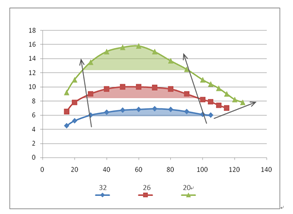
Schematic diagram of the relationship between unit cooling capacity and cooling water temperature
3. Reasonable Allocation of Host and Plate Exchanger Output in Partial Natural Cooling Mode
In systems where the plate exchanger and the main chiller are connected in parallel, there is no partial natural cooling mode where the two are mixed. Therefore, this section mainly considers the series mode where the plate exchanger is located upstream of the main unit. In this mode, the water temperature entering the evaporator of the main chiller will be lower than the designed system return water temperature.
With the increase of outdoor cooling resources, the BA system can further reduce the cooling water temperature, which means that the cooling capacity of the plate exchanger increases, while the cooling capacity of the main chiller decreases. If the unit current percentage is simply used as the basis for increasing or decreasing the number of units, the cooling capacity output of the plate exchanger may be incorrectly ignored, resulting in a unit reduction operation. The BA system should consider matching the overall cooling demand based on the total cooling capacity of both.
A continuous decrease in the outdoor wet-bulb temperature will force the plate exchanger upstream to bear more of the load, in other words, the chiller unit may enter the low-load surge zone. To avoid this phenomenon, the BA system should control the allocation of cooling capacity between the plate exchanger and the main unit by limiting the outlet water temperature of the plate exchanger's chilled water side. Specifically, according to the characteristics of the chiller unit used, the cooling tower fan speed and the number of fans should be controlled to control the outlet water temperature of the secondary side of the plate exchanger to limit the inlet and outlet water temperature difference of the chiller unit evaporator. This avoids chiller surge while reducing cooling tower power consumption.
4. Protection of the Main Chiller in Partial Natural Cooling Mode
Before entering the full natural cooling mode, during the partial natural cooling mode, as the outdoor temperature decreases, even if the cooling tower fan gradually decreases to stop, there will still be a relatively long period of time when the cooling water temperature entering the condenser of the main chiller is lower than the cooling water temperature acceptable under the normal operating conditions of the main unit. The lower the designed system chilled water supply temperature, the longer and more severe this operating condition will last.
If this situation is ignored, it will affect the pressure difference between the evaporator and condenser of the main chiller, causing shutdown protection. Therefore, in addition to considering the lowest condenser inlet water temperature acceptable by the main chiller when selecting the main chiller, adopting variable flow condenser inlet water from the control logic is also a means. Specifically, the pressure difference between the evaporator and condenser needs to be monitored in real time. When the cooling water temperature is low, the bypass valve opening between the inlet and outlet of the condenser is controlled to reduce the water flow entering the condenser, keeping the condenser in a low-temperature, low-flow state to maintain the pressure difference to reach its set value. This allows the main chiller to continue operating until the standard for entering full natural cooling is reached.
5. Avoiding Frequent Start-Stop of the Main Chiller
When controlling the number of chiller units in operation, and when switching directly between partial natural cooling and full natural cooling modes, this issue is involved, that is, overly sensitive control conditions should be avoided to reduce the possibility of frequent start-stop of the main unit, thereby extending the service life of electromechanical facilities.
In the logic of BA system unit number control, when the load-side demand exceeds the add-subtract unit switching point, the command to increase or decrease the number of units should not be executed immediately, but the trend of this exceeding phenomenon should be observed within a set time period, and the control output should be performed after confirming the growth trend of the load. Similarly, after the outdoor wet-bulb temperature exceeds the switching point of the full natural cooling mode, the mode should not be switched directly, but the temperature trend and even recent weather characteristics should be considered before execution, ensuring that the chiller units will not be changed again within several hours after being started or stopped.
6. Energy Saving Potential of Variable Frequency Chilled Water Pumps
Regardless of whether a two-stage pump or a single-stage pump with variable frequency is used, the BA system will control the pump speed and the number of pumps to maintain a stable system pressure difference. However, the rationality of the setting value of this pressure difference affects the energy-saving performance of the system but is often overlooked.
From the initial operation of a small number of data center rooms to the full commissioning of all rooms, the system resistance changes continuously. Maintaining the pressure differential of the main pipeline (differential pressure transmitters are usually installed in the main pipeline supply and return water) does not mean that the pressure differential before and after the terminal water valve remains unchanged. If the set pressure differential is too small, it may not be able to meet the needs of some rooms with relatively high loads or hot and cold aisles; if the set value is too large, although hotspots no longer appear everywhere, energy consumption is also sacrificed.
This part of the energy-saving space can be explored by dynamically optimizing the pressure differential set value. The premise is that the BA system obtains the opening information of all terminal valves. If it is detected that most valves are at a low opening, it means that the pressure differential is too large, and there is an opportunity to reduce the set value. Conversely, if most valves are at a high opening, or even some valves are always at 100% opening, it can be judged that the pressure differential setting is too low, and it should be increased. The BA system can consider the above dynamic adjustment to further contribute to the energy saving of the variable frequency pump.
On the other hand, monitoring the opening of all terminal valves also provides an opportunity to observe whether there are any imbalance problems in the system. If there are always individual terminals at higher or lower openings, which are significantly different from the status of other terminals, the maintenance personnel can regard it as a potential problem and focus on troubleshooting.
7. Using the cold storage tank during low load periods
In the initial stage of data center operation, there is often a temporarily smaller load. Even if the number of cold standby units is controlled, and a single refrigeration unit is used for cooling, it may enter the surge area. During this period, by controlling the logic, intermittently charging/discharging the cold storage tank can help avoid the operation of the host at low load.
To achieve this function, two preparations need to be made. First, let the BA system first understand how many modular data centers are currently enabled (only one or two data centers may be enabled in the initial operation), and thus judge the refrigeration needs of these modular data centers under full load. This demand will be used as safety stock, and when the cold storage tank is used for cooling, it should be ensured that it will not be used, that is, the energy storage status of the cold storage tank should end the cooling mode before reaching the safety stock. Secondly, let the automatic control system monitor the temperature distribution of the temperature jump layer of the cold storage tank, and then estimate the current energy storage status according to the characteristics of the cold storage tank.
With the above conditions, the BA system can formulate logic to allow the refrigeration unit to charge the unfilled cold storage tank as part of the load side when the load is small. At this time, the refrigeration unit will regard the sum of the terminal load and the cold storage tank load as the target, and operate at a higher efficiency under a larger load. When the program judges that the energy storage status of the cold storage tank is relatively full, or the total load causes one unit to enter a lower load again, it can choose to shut down the unit and use the cold storage tank to cool to maintain the needs of the IT modular data center until the energy storage status of the cold storage tank is close to the previously set safety stock.
In order to avoid the alternation of the above two states too frequently, during the charging period, if the total load exceeds the refrigeration capacity of one unit, the program should not use the conventional number of units control logic, that is, it should not load the second unit. Otherwise, the cold storage tank will be quickly filled, and the refrigeration unit will need to stop shortly after operation, which is not beneficial to the protection of the unit.
Source: Data Center Cold Source Technology White Paper
Disclaimer: Some of the publicly available information collected on this website comes from the Internet. The purpose of reprinting is to convey more information and for online sharing. It does not represent this website's agreement with its views or its responsibility for its authenticity, nor does it constitute any other suggestions. The content of the article is for reference only. If you find any works on the website that infringe your intellectual property rights, please contact us, and we will modify or delete them in a timely manner.
Advertising Space

DencoHappel (Beijing) Refrigeration Technology Co., Ltd.
Address: Greenland Qihang International North District, Houshayushu, Shunyi District, Beijing
Email: info.cn@dencohappelgroup.com
Scan the mobile app to view
Copyright: Degao Hebai (Beijing) Refrigeration Technology Co., Ltd Powered by:CEglobal
在线客服添加返回顶部
图片alt标题设置: DencoHappel (Beijing) Refrigeration Technology Co., Ltd.
循环体没有内容时: The information is being compiled, please look forward to it.
CSS / JS 文件放置地